·Plastic inspection well Installation and construction
1.1 General provisions
1.1.1 Drainage should be installed before construction, and drainage pipeline engineering and technical work work.
1.1.2 Construction unit should prepare detailed construction organization plan.
1.1.3 The construction unit should be designed according to the documentation "plastic drainage inspection well project preparation table".
1.1.4 Plastic drainage inspection well project preparation table should be according to the number of wells to inspect well fill.
1.1.5 Inspection of the inspection of the inspection of the well components shall be carried out as per the following requirements:
1. Inspection of parts of the product quality certificate and inspection report.
2. Inspection parts specifications model, interface diameter, nozzle number.
3. Check the appearance quality, size deviation, etc.
1.1.6 After the inspection of parts inspection wells, should be ordered according to the number of well placed.
1.1.7 Check the foundation of well bottom seat before the bottom of the well bottom seat to be checked and accepted. When it is found that the foundation is disturbed, super dug, soaked in water, or the existence of poor foundation, poor soil layer, should be treated to meet the design requirements, the construction can be carried out.
1.1.8 Check the well parts should use artificial or mechanical equipment under the lifting ditch. Hoisting should adopt non - metallic rope (belt) hoisting.
1.1.9 Inspection hole seat connected with the pipeline, the bottom seat pit over excavation should be timely and graded sand gravel or sand backfill compaction, and meet the design requirements.
1.1.10 When the bottom hole seat of the inspection well is connected with the pipe, the special tightening machine should be used for connection, but the attention should not be paid to the bad influence on the connected pipeline.
1.1.11 Inspection of the connection between the various components, as well as the connection between the water and the drainage pipe must ensure long-term reliable sealing performance, and has a certain ability to resist uneven settlement.
1.1.12 Inspection well in the installation, backfill process, the bottom of the water may not have water or frozen.
1.1.13 Inspection of the installation of Ii should be carried out simultaneously with the road pavement construction.
1.1.14 PVC and PP inspection wells in the winter construction, the temperature should be higher than -5.
1.1.15 When the inspection well and the drainage pipe are connected with the elastic rubber sealing ring, the rubber ring is in the elastic deformation range under the condition of bearing outside force.
1.2 Foundation pit and foundation
1.2.1 Pit excavation, should be carried out after the completion of the construction of the foundation of the drainage pipeline. The bottom hole base should be in line with the main line of the drain line.
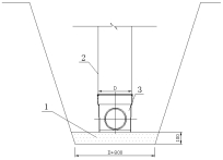
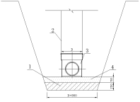
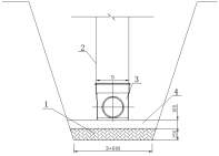
1.2.2 At the bottom of the base of the practice should be according to the geological data and backfill under the drag force, determined by the structural design, and should not be less than the following minimum requirements:
1. Sand, rocks, gravel soil, can fill in the pit with thickness not less than 100mm in the sand cushion, see figure 1.2.2-1:

Figure 1.2.2-1 well bottom seat Foundation (1)
1 - sand cushion; 2 – Well wall 3 - seat bottom wall
2. Soft clay soil, fill in the hole with 150mm crushed stone or gravel shop (diameter 5 mm to 40 mm) layer, tamped zaipu 50mm sand cushion, as shown in figure 1.2.2-2:

Figure 1.2.2-2 well bottom base (two)
1 - crushed stone or gravel;2 - wall; 3 - bottom seat cushion; 4 – sand
3. Collapsible loess soil, foundation pit soil compaction, foreshadowing the 100mm to 150mm of Panax notoginseng lime soil cushion and lay a solid foundation for, tamped zaipu 100mm sand cushion, as shown in figure 1.2.2-3:

Figure 1.2.2-3 well bottom base (three)
1 - shaft lining; 2 Wall;3 - bottom seat; 4 - sand cushion
4. The thickness of sand and gravel cushion should not be less than the thickness of the cushion layer, and the compaction coefficient should not be less than 0.95.
1.2.3 Heavy mud tank manhole excavation, according to sink the mud tank size of partial excavation and fill the shop 100mm in sand cushion.
1.3 Bottom hole base and nozzle
1.3.1 Check the connection and installation sequence of the well and the drain pipe:
1. The construction area should be installed in the order of the upstream to the downstream of the pipeline.
2. The municipal pipeline should be installed in the order of the upstream and downstream of the pipeline.
3. Installation in the order of the well to the pipe to the well.
4. The central position of the well is first determined on the axis of the pipeline foundation, the foundation pit is excavated by the size of the bottom hole base, and the bottom seat is adjusted to adjust the height of the bottom seat, and then the bottom hole seat is installed and connected with the pipeline.
1.3.2 The installation of the well bottom hole seat shall comply with the following provisions:
1. Bottom hole in the bottom of the ditch, to respond to the bottom of the bottom seat number, specifications, pipe diameter, etc.
2. Under the bottom of the ditch, the first use of temporary block, the bottom of the bottom of the center, the main axis, the bottom of the bottom level and the level of adjustment. When it meets the design requirements, the sand bags and other measures for temporary fixation and filling in the sand, remove the block.
3. When installing the bottom hole, it is not allowed to disturbed the foundation cushion. Effective remedial measures should be taken when the foundation bed is damaged.
1.3.3 The correction and fixation of the bottom hole shall be carried out according to the following provisions:
1. Level correction can be carried out using the bubble level. Correction, the first school pipeline axis direction, after school and the vertical direction of the pipe line.
2. The bottom seat can be used for cable axis correction.
3. Bottom hole of the elevation correction, should be carried out using the level.
4. In the process of correction, then the available amount of sand will be the bottom seat fixed temporary.
1.3.4 On the bottom hole with inverted cavity, it is appropriate to use C15 concrete filled with and after curing, the next ditch installation.
1.3.5 The connection between the bottom hole base and the pipe shall be in compliance with the requirements of the current standard and shall be carried out as per the following requirements:
1. The connection construction method of the interface should be adapted to the construction method of pipe connection.
2. The bottom seat interface and plastic pipe connection requires reducing, should adopt the adjustable joint. When the water inlet pipe diameter is smaller than that of the bottom hole seat, the top of the pipe should be flat.
3. When the bottom hole base is connected with the non plastic pipe, special transition joints shall be used for connection. When the transition joint is connected with the bottom hole socket, and the non plastic pipe is connected with the non plastic pipe, the thermal contraction belt is adopted to reinforce the connection.
4. When the bottom hole seat interface and the steel strip reinforced spiral pipe, the special transition joint should be used for connection. When the transition joint is connected with the bottom hole socket, and the steel strip reinforced spiral pipe is welded connection, the thermal contraction belt is adopted.
5. When connecting with other pipe, the connecting method of current standard and standard should be adopted.
1.4 Wall pipe, wall cone nozzle
1.4.1 The length of the tube wall should be based on the inspection wells and depth inspection manhole cover seat design elevation determined by calculation.
1.4.2 Plastic casing pipe cutting, the incision should be flat and vertical pipe axis, can leave the surplus length of certain.
1.4.3 The connection between the shaft lining pipe and the bottom hole seat is connected with the connection of the elastic rubber sealing ring or the thermal contraction sleeve (belt).
1.4.4 The installation and connection of the shaft wall pipe shall be carried out according to the following requirements:
1. The connection between the shaft wall and the bottom hole should be carried out after the bottom hole is installed.
2. When inserted, should use special tools to tighten, do not use hammer directly beat, and timely adjust the verticality of tube wall.
3. When the bottom seat location center and tube wall verticality adjustment, should be promptly fixed, and temporary plugging pipe.
4. In response to the wall before splicing, section size of inner tube were measured and recorded.
1.4.5 The wall of pipe access drainage pipes, according to the number of branch pipes, the wall or wall joint connection.
1.4.6 On the tube wall, the wall joint is connected with a drainage pipe, at the scene open hole connection, but two movable joint edge spacing should not be less than 100mm; access drainage branch pipe diameter should not be more than 315 mm. At the same time, the joint shall not reverse slope.
1.4.7 In the straight wall inspection wells, the wall pipes access drainage pipes, can be carried out in the following order:
1. After installation at the bottom of the well.
2. According to the branch is connected with the bottom of the tube elevation and bottom seat bearing mouth bottom elevation difference, interception of the first section casing pipe length, and insert it into the bottom seat socket.
3. Then the wall pipes inserted into the first section of pipe wall, and sealing pipe access interface.
4. Then the second section wall pipe is inserted into the wall pipes, and timely closure of nozzle.
5. Should timely adjust the verticality inspection wells, and to be fixed.
1.4.8 In the closing type inspection wells, the wall pipes access drainage pipes, should be in accordance with the following provisions:
1. In the wall at the same elevation, access from different directions 1 ~ 3 drainage pipes should be in the shaft wall pipe fitting, and the use of special equipment to tighten connection, connections shall not reverse slope.
2. In the wall at the same elevation, access from the same direction 2 ~ 3 drainage pipes, should first use drainage pipe pieces after confluence, then through the sidewall over connecting inspection wells, and the special equipment to tighten connection joints shall not reverse slope.
1.4.9 In the closing type inspection wells, installation of wall closing cone, should be carried out according to the following requirements:
1. The wall is so cone height should be carried out according to the design requirements.
2. Using special tool sidewall closing cone is installed on a well wall pipe, and then connected to the wellbore.
3. Wellbore length should be set aside a certain amount of surplus, and higher than the ground.
1.4.10 The shaft wall (cylinder) installed in the inspection wells, should be based on the situation of groundwater in the trench, in time to take measures to prevent floating.
1.5 Rain water outlet
1.5.1 The installation of rain water ports shall be carried out in the following order:
1. The completion of road subgrade or lawn ground leveling, trench excavation and rain rain water pipe.
2. According to the elevation of rain and rain pipe slope, hole in pipe wall rainwater inspection wells, and install the shaft joint.
3. The wall joint is installed, and the connection and the laying of water pipes, and temporary plugging rainwater branch pipe.
4. In the installation of road edge stone gully of foundation pit excavation and placed a gully, connect the rainwater branch, with fine sand infill and solid.
1.5.2 When the water outlet is placed on the road, the height of the road should be adjusted according to the height of the road surface, and the appropriate measures should be taken to protect it.
1.6 Closed water test
1.6.1 The closed water test of inspection wells should be carried out simultaneously with the closed water test of the drainage pipeline system.
1.6.2 The method of closed water test is the same as the test method of the drainage pipeline system.
1.6.3 The results of closed water test shall be recorded in the well. If there is leakage, we should take effective measures to repair.
1.7 Backill
1.7.1 Backfill shall be carried out after closing the water test.
1.7.2 Before backfill, sand bag and other measures can be used to carry out temporary fixed inspection wells, and there is no water in the pit.
1.7.3 Check the longitudinal length of the backfill, 3 times the diameter of each side of the shaft wall, the lateral width of the backfill, to both sides of the groove, and the width of each side backfill material is not less than 400mm.
1.7.4 Backfill materials shall not be used in silt, silt soil, collapsible soil, expansive soil, frozen soil, the maximum size of not more than 40mm, and no stones, bricks and other sharp objects. The compaction coefficient is 0.95, which is not less than the design requirements of road or ground.
1.7.5 The backfill around the borehole wall should be constructed by artificial layering, symmetrical backfill and compaction. Should strictly control the initial deformation of the shaft wall, mechanical backfill is prohibited.
1.7.6 Range of around more than or equal to the width of 100mm pipe hole (drum), appropriate were backfilled with coarse sand, sand and gravel, slag or the slag lime soil non frost heave material. When the wall (tube) using polyethylene winding structure wall pipe, wall (tube) tube range of around more than or equal to the width of 100mm and non frost heave material should be applied in the backfill.
1.7.7 Backfill time should be selected in the daily temperature change in a small period of time.
1.8 The bearing plate and the manhole cover
1.8.1 The installation of the bearing plate should be in the same time as the road pavement construction, and the prefabricated reinforced concrete bearing plate should be adopted.
1.8.2 The diameter of the orifice plate should be larger than the outer diameter of the shaft (cylinder). The distance between the edge of the bearing plate and the upper edge of the wellbore should not be less than 100mm.
1.8.3 The cushion of 300mm should be laid on the bottom of the bearing plate. The cushion material can be used in roadbed, graded sand gravel material or C20 concrete.
1.8.4 Before the laying of the bearing plate cushion should ring placed on the outside of the wall (cylinder), and in the wall (drum) and the gap between ring good anti seepage measures.
1.8.5 Before the bearing plate hoisting is in position, should first use the small stakes in the cushion of positioning, ensure the concentric bearing plate hole and shaft (tube).
1.8.6 The road pavement construction, the inspection manhole cover is arranged on the bearing plate.